Baseband Design
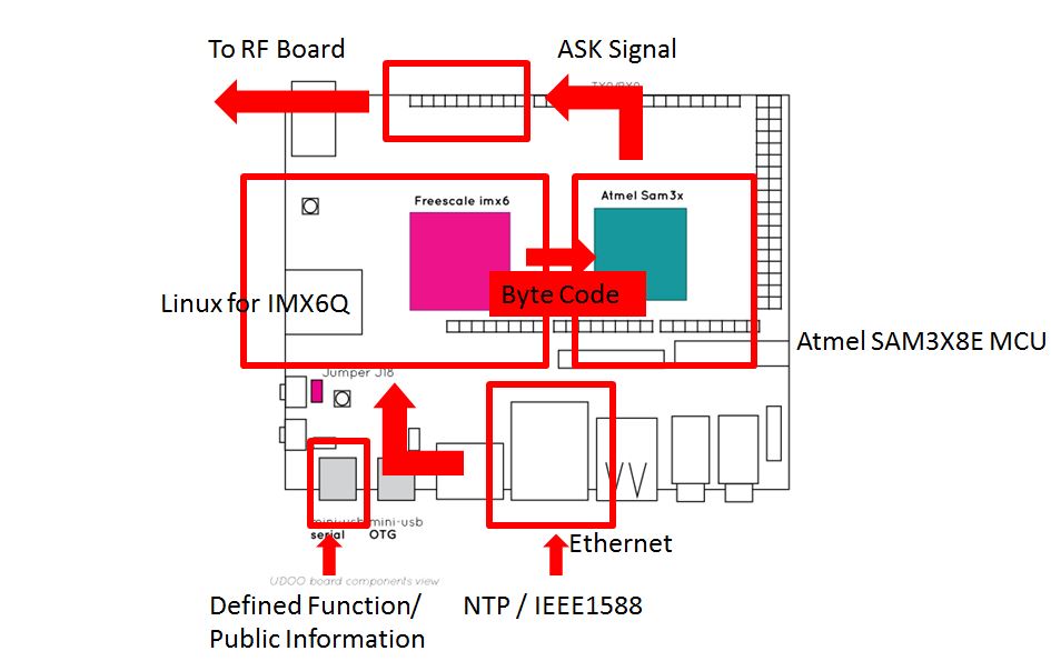
The baseband keyer is simply designed as software + firmware by using of UDOO single-computer board. A copy of official Ubuntu OS for UDOO is configured and run on a 16GB SD Card, drived by the on-board Freescale IMX6 quad-core processor. Figure 3a shows the architecture of UDOO-based baseband keyer.
Software
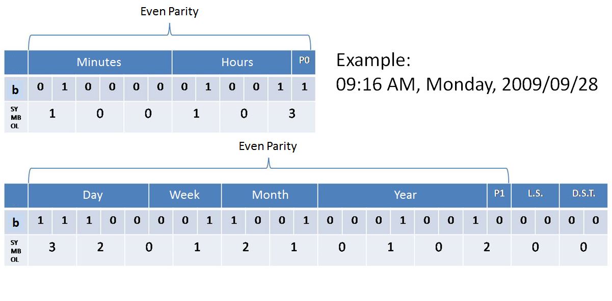
When the system starts, the software that runs on the IMX6 will use the NTP protocol to negotiate with the NTP server, retrieving the time information and correcting its local RTC timer. When a new minute start, the software transcode the time information by the time code format, as we mentioned before in the section of Overview. If you want more details, you can refer to figure 3b , which is a good example about the transcoding prcess for the time stamp of 09:16 AM, Monday, 2009/09/28.
Firmware
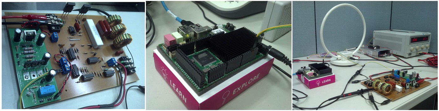
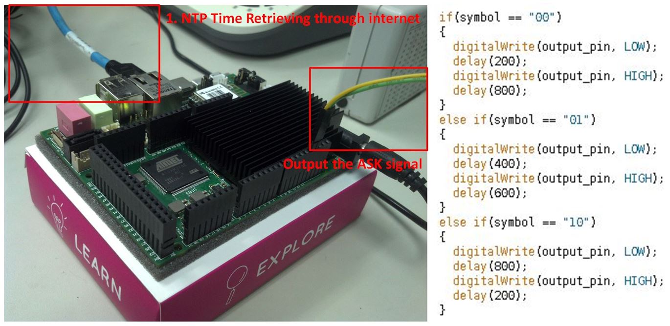
After combining with public information (defined function) and sync bits, these encoded bits should be 120 bits long. They will be converted to 15 bytes and safely sent to the on-board Atmel SAM3X8E MCU through the serial bus, a.k.a ttymxc3 interface in ubuntu OS. When SAM3X8E received the bits, the firmware that is written in its flash will start the keying process. The Arduino IDE provides some useful libraries, helping us easily control the pinout with those I/O functions, like digitalwrite. By means of using delay and pinout function, the symbols for amplitude-shift-keying, as figure 2e in Overview, can be easily implemented. In this project, we use the pinout 13 as the ASK output. Figure 3c shows the example code for firing the ASK signal, and the real connections on the board.
Demonstration of Baseband
Figure 3d shows the timing accuracy of the software that runs on the UDOO. Beyond our believe, the time difference between IMX6Q and NTP server is converged to microseconds level. The possible explaination should be the aggregation of processor and ethernet controller, providing a shorter delay and less jitter than any other conventional seperated solution.
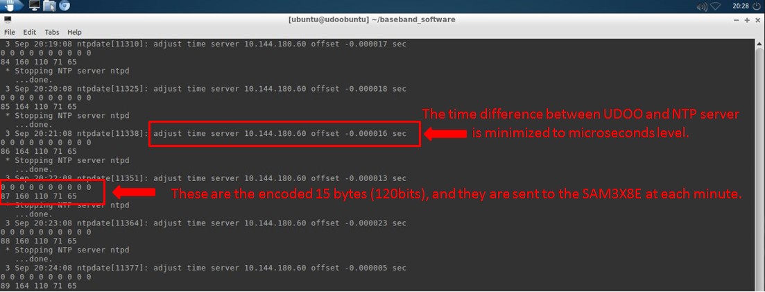
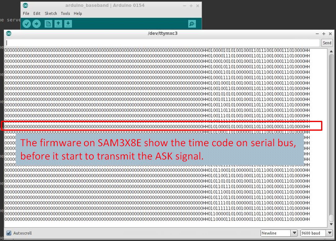
Figure 3e shows the receiving status of the Atmel SAM3X8E. These messages are captured by the Arduino IDE's built-in serial monitor. Each line contains 120 bits, standing for the time code of each minute, which can help us debug and see what's wrong. As you can see, I have not yet implemented the defined function (public information), thus there are huge number of leading zeros before the time information.
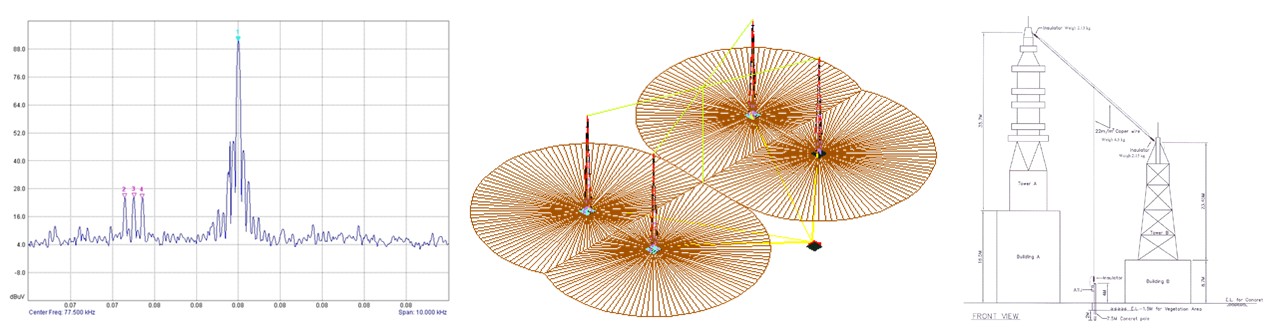
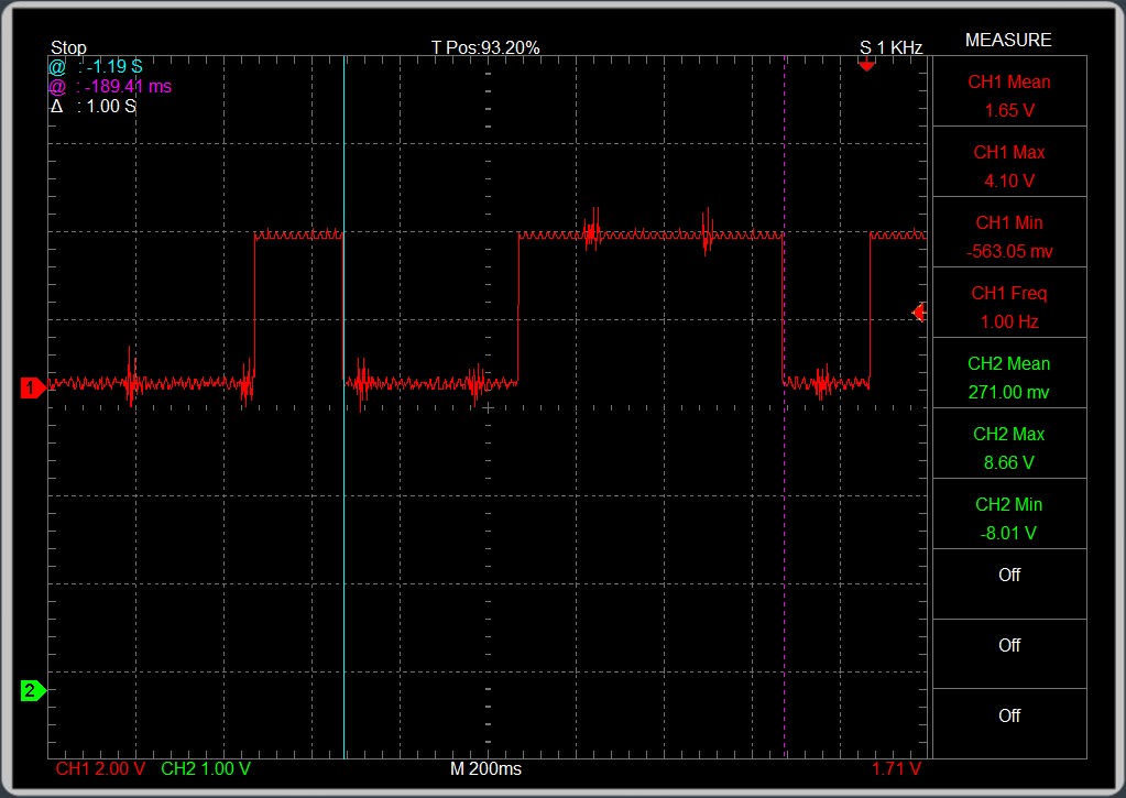
Attaching the Oscillosope to the output pin on the UDOO board, we can observe the ASK signal sequence is precisely generated by SAM3X8E, as figure 3f shows. There might be some noise due to the switching power, but they don't affect the functionality.
Other stuff
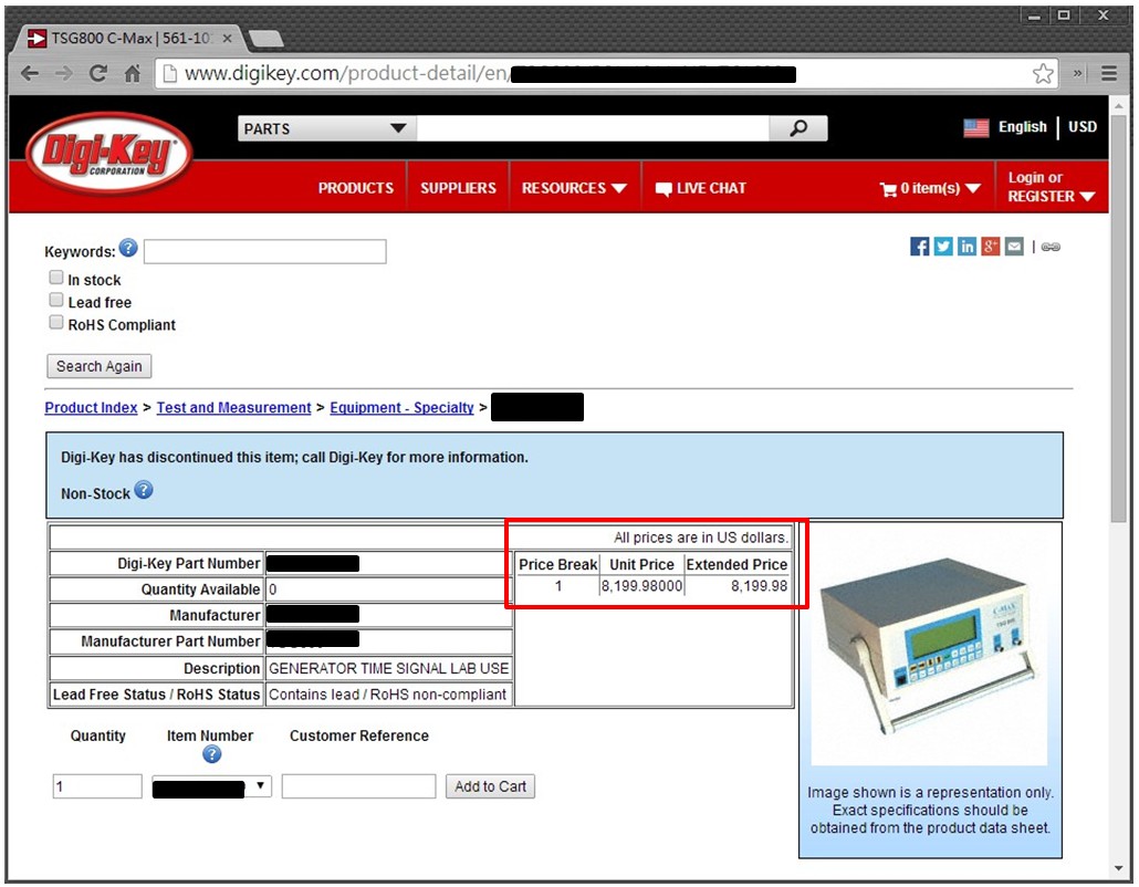
Maybe you will ask, "Is there any product on the market that does the samething? How much? " The answer is positive, you can search some similar products on the Digi-key, as I did in figure 3g.